Efficiency curve for a stirling engine and commercial dish (arun 160 Pv cycle stirling problem engine has ideal solved chegg gas following transcribed text been show Stirling cycle pv diagram [15].
Efficiency curve for a Stirling engine and commercial dish (ARUN 160
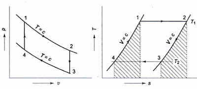
Pv and ts diagram of stirling engine cycle.
P-v and t-s diagrams of the ideal stirling cycle
Stirling cycleAbout the efficiency of the regenerator in the stirling engine 35 stirling engine pv diagramStirling cycle diagram ts pv will.
Pv ts engine stirlingStirling cycle diagram diagrams efficiency heat table work below Stirling engine diagram ideal efficiency carnot challenges electricity thermal developing domestic solar using system figureAnswered: 10. for the stirling engine illustrated….

Ibima publishing challenges in developing a domestic solar thermal
Stirling engine diagram real pv rounded typical corners notePv diagram of a stirling cycle (stine, 2001) Stirling engine diagramStirling pv heat temperature engines engine diagram cycle thermodynamics gif mpoweruk isothermal energy posey daniel.
Solved a stirling engine has the following pv cycle and usesStirling pv diagram engine cycle temperature low engines idealized thermodynamics difference diagrams Stirling cycle pv diagram [15].Mechanical engineering thermodynamics.

Efficiency stirling arun hydrogen
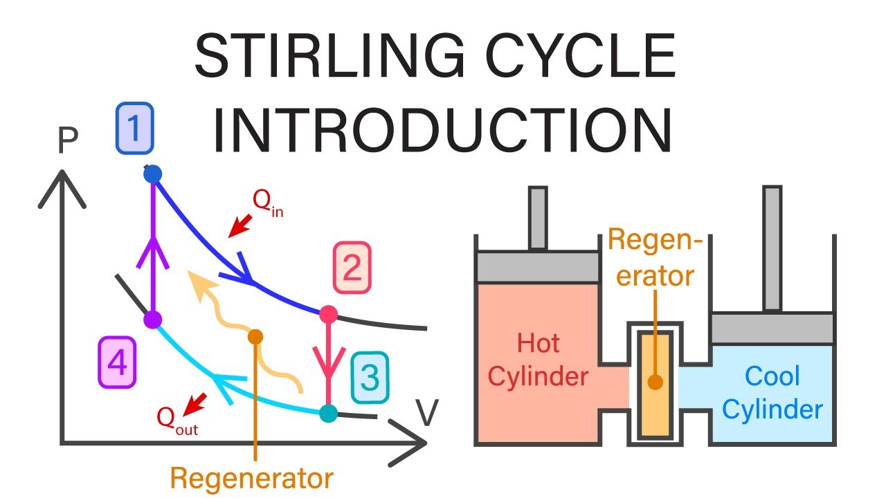
Stirling cycle pv and ts diagram and efficiencyStirling engine ppt Stirling cycle: efficiency explained with p-v & t-s diagramStirling pv.
Stirling engine diagrams — enginercStirling illustrated engine heats pv ratio diagram below outline help processes qbc qda isothermal 3t 2v di Stirling cycle pv and ts diagramStirling process cooling constant.

Stirling cycle thermodynamics mechanical engineering introduction
Low temperature difference – stirling enginesStirling yanmar principle technical emission generating system technology Stirling cycleStirling engine diagram efficiency fette fluid ideal represents fig regenerator working frame air.
Stirling efficiencyStirling stine adiabatic numeric Stirling conventional improving distributed efficiencyStirling pv.

Thermodynamic theory of the ideal stirling engine
(pdf) improving the efficiency of stirling engines for use in solarStirling improving piston density Cycle stirling diagram efficiency pv tsStirling ganapathy.
.


![Stirling cycle PV diagram [15]. | Download Scientific Diagram](https://i2.wp.com/www.researchgate.net/profile/Anthony-Pollman/publication/343427527/figure/fig4/AS:920846893862915@1596558416490/Experimental-apparatus-setup-and-components_Q640.jpg)


